
Introduction
Some people think that if you do agile software development you do not need to model your application and write UML and architecture documentation. This is not true. You even have to do more of it – you only do it at a different time. You do not do all the modeling beforehand and then build your application – you always design a little and, subsequently, develop a little. If you have several people involved in different projects, it is even more important that you have a consistent way to model and document your requirements and software architecture. Using Visual Studio (VS) 2010 and Team Foundation Sever (TFS) for the development, it is advisable to also use VS for modeling.
Scenario
In our samples we will use the following scenario to model a small application and to demonstrate the use of our diagrams.
A swabian car manufacturer has contracted us to develop an invest approval workflow system. The system was supposed to be easy to use and all employees should be able to request an investment.
Model Requirements
The first step is to model our requirements. We create a VS Modeling Project and design the first basic use cases.
Go to File New Project and add a new blank solution.

Figure 1: Create blank solution
Add a modeling project to the new solution by right clicking the solution and selecting “Add” “New Project…”. Select Modeling Project and enter the name for the project. An extension of “Model” or “Design” is a common extension to use for this project.
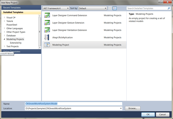
Figure 2: Add modeling project
Model basic use cases
Now we have our modeling project in place and we can add the first use case diagrams. Under “Architecture” select “New Diagram” and add a new UML Use Case Diagram.
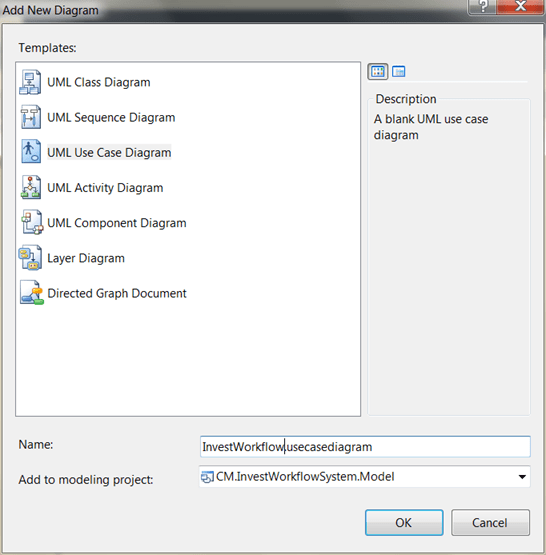
Figure 3: Add UML Use Case Diagram
In our toolbox we have the UML 2.0 objects needed to create our first use case. We can add actors, use cases and can associate them with each other. Our basic use case would look like in Figure 4. We have employees and managers as actors and the use case “request investment”. We can add comments to indicate things that need to be done in future or to clarify things in the diagram.

Figure 4: Create Basic Use Case
Now we go down one level and create a use case for the investment request. Add a new use case diagram and name it “Request investment”. The use case could look like in Figure 5.

Figure 5: Create deeper level use case
In order to use our diagrams for navigation, we can add “Artifact” elements and link them to other resources. We can also add e.g. Visio Charts and link them here in the diagrams. We will now add an artifact to the basic use case diagram. Use the “Hyperlink” property to add the path to the diagram like in Figure 6. Our diagrams look now like in Figure 7.

Figure 6: Add Hyperlink
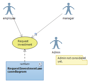
Figure 7: Use case diagram with hyperlink
You can now navigate to the other use case by double clicking the artifact. You can build a navigation hierarchy in your diagrams with this technique.
You can achieve the same thing by dragging diagrams from the solution explorer to your use case. It is best practice to add a dependency from the artifact to the use case.
Create User Stories from Use Cases
Now we have our first use cases in place and we want to create our user stories (Requirements if you use CMMI) and link them to the use case. Right click the use case in our diagram and select “Create Workitem” “User Story”. Fill out the user story and save it. Your use case now displays a small sign like in Figure 8 that indicates a linked work item. You can right click the use case and select “View Work Items…” to view all the related work items.

Figure 8: Use case with work item
Create Activity Diagram
You can use an activity diagram to define how you plan to implement the use cases. Add an activity diagram to the project.

Figure 9: Add Activity Diagram
Add the artifacts from the toolbox into the diagram. Start with the initial node. Add actions in a sequence to the diagram. Use decision and merge nodes to create decision trees. Use forks to run activities in parallel. See http://msdn.microsoft.com/en-us/library/dd409360.aspx for a complete reference to the elements you can use in the diagram. A basic diagram could look like in Figure 10.

Figure 10: Activity Diagram
Like in the use case diagram you can also link every element to work items. You can e.g. relate an activity with task and assign it to a user. The task can either be a development task or a design task that relates to the diagram.
Model Solution Architecture
Now that we have modeled our requirements and start implementing the user stories we need to create the architecture for our application. A good starting point is to define a “pig picture” diagram that outlines our technical choices. We can use a layer diagram for this.
For a brief introduction to application architectures see the Microsoft Application Architecture Guide, 2nd Edition.
Define Big Picture / High Level Design
Create a new layer diagram and lay out the architecture of the application. We want our application to integrate in the existing SharePoint environment. We will access the application with the browser and we also will need to make a call into SAP. Our big picture could look like this.

Figure 11: Big Picture
Some of the ‘rules’ you should consider when modeling applications are:
- Separation of concerns
- Single Responsibility principle
- Principle of Least Knowledge
- Don’t repeat yourself (DRY)
- Minimize upfront design
- Keep design patterns consistent within each layer.
- Do not duplicate functionality within an application.
- Prefer composition to inheritance
- Establish a coding style and naming convention for development
- Use abstraction to implement loose coupling between layers.
- Be explicit about how layers communicate with each other
- Do not mix different types of components in the same logical layer
- Keep crosscutting code abstracted from the application business logic as far as possible
See Modeling the Architecture of a Software System and http://www.arc42.com/ for help to documenting and creating software architecture. You can install the ApplicationArchitectureGuideLayerDiagrams.vsix and build your application out of one of the defined archetypes, like SharePoint LOB- or Web Application, or use the other templates.
Define Detailed Layer Diagram
Now that we have defined the big picture of our application, we can lay out the structure for our application. We will also use a layer diagram for this. This time it will only contain the layers that will be in our application. A detailed layer diagram could look like Figure 12. Our UI will implement the Model-View-ViewModel pattern. The model will also be used as a DTO (Data Transfer Object) and must therefore be in the crosscutting layer.

Figure 12: Detailed Layer Diagram
Validate Solution using the Layer Diagram
Now that we have created our architecture we can begin to set up our projects. We could model our solution in the model explorer and then generate our code, but this goes beyond the scope of this post.
I have created the basic assemblies with some sample classes like in Figure 1.

Figure 13: Basic solution structure
We can now open the architecture explorer (see Figure 14). In the solution view we see our projects. We can drag the projects to the corresponding layer in our diagram (See Figure 12).
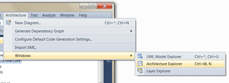
Figure 14: Open Architecture explorer
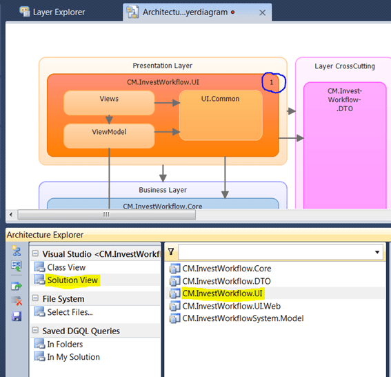
Figure 15: Drag Projects to diagram
If we switch now to the layer explorer we can see that assembly was added to the diagram.

Figure 16: Assembly in layer explorer.
Notice the one in the right corner of the layer. This indicates the existence of objects that are being validated. Repeat the last step for all assemblies in your solution. Right-click you diagram an select “Validate Architecture” to validate your existing code. Right now there should be no errors and the output window tells you that the validation has passed.
In the class view you have all the namespaces in your application. Drag the namespaces to the corresponding layers. You can also drag single classes to layers.
To automate the validation you can set the property of the modeling project (see Figure 17). To use the validation in a TFS team build you have to set an additional build parameter: /p:ValidateArchitecture=true
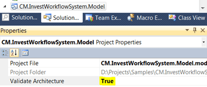
Figure 17: Validate Architecture on Build
If you now add a reference, that is not allowed, an error will be generated. If we, for example, add a method to our UI.Common.Utilities that reference a UI.ViewModel the build will fail (see Figure 18). The same happens if you add an assembly reference directly from the UI to the data layer.

Figure 18: Validation Output
Conclusion
This post only gave a brief introduction how to model your requirements and how to create your application architecture. It does not cover code generation or investigating existing code. These topics will be covered in separate posts.
I think the task of creating and documenting your application architecture is very important if you work in agile teams. Visual Studio is a great tool and integrates perfectly in your TFS environment.
